It’s wonderful that you’re reading this blog, we would like to cheer you on installing a Solar Power plant. Are you wondering ‘What’s next?’
Worry not, we got you covered.
Source
Installation of a Solar power plant is a 25 years investment, which sounds very easy when it comes to Return on Investments as the payback generally spans from 4.5 to 5 years, where your investment can reap profits for the next 20 years of your PV plant’s life. Isn’t it an easy choice to make as a buyer? Or are we missing something here?
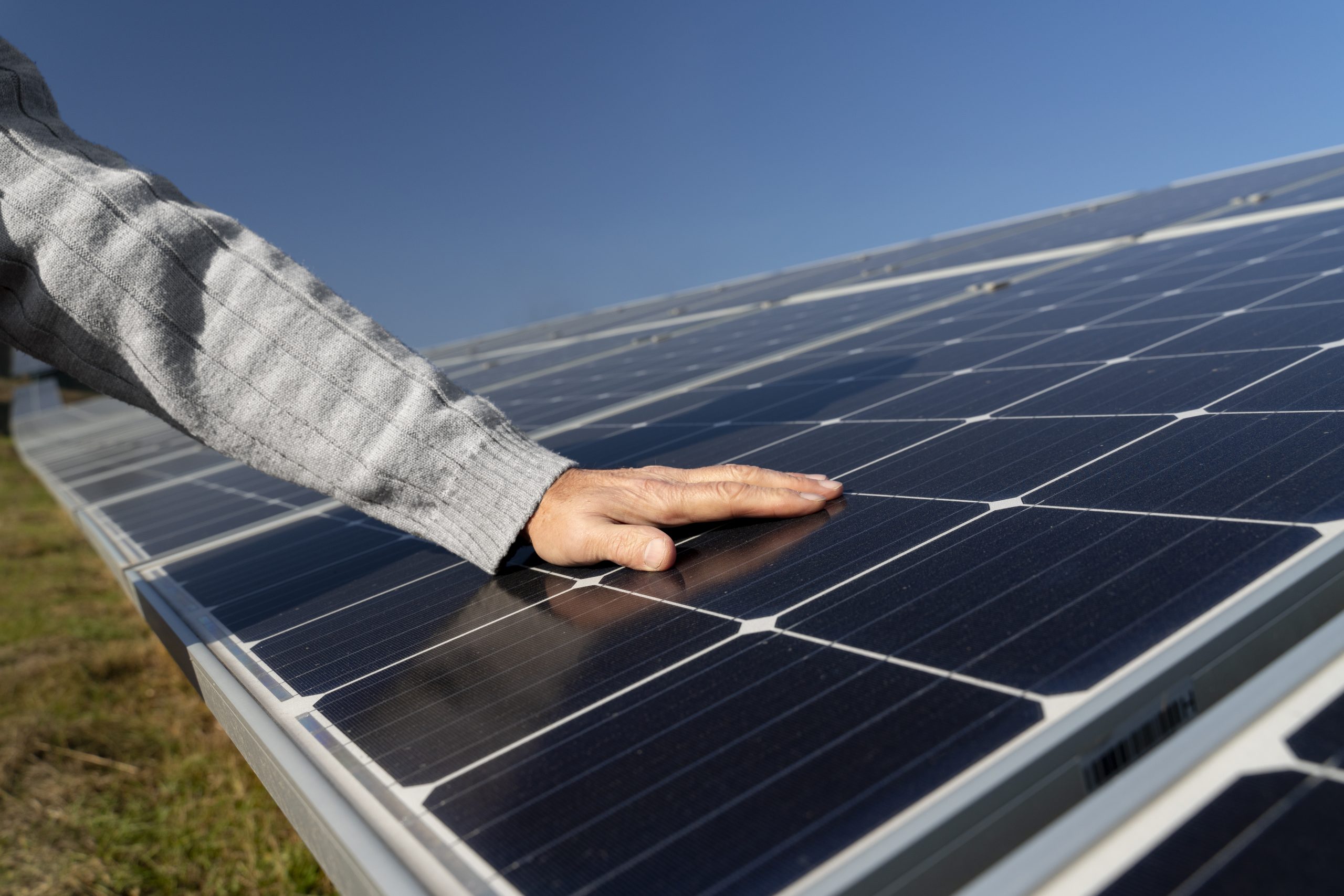
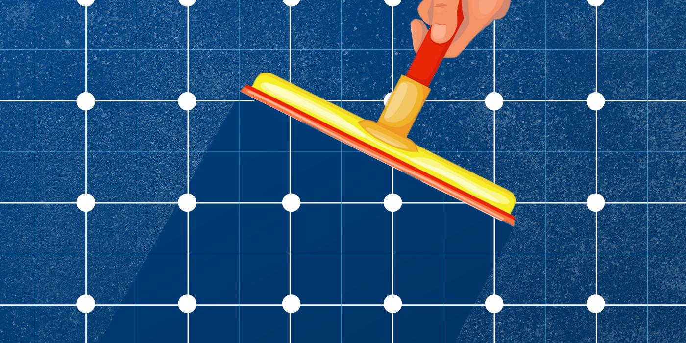
Although solar power plants require lesser maintenance as compared to their counterpart energy generation sources, there is a significant requirement to maintain these power plants in order to make them withstand a variety of natural forces in their lifetime.
An overview of solar panel maintenance
- A tilted solar panel requires little maintenance since rain can wash away any debris.
- Two to four times a year is generally recommended for solar panel cleaning
- Using a monitoring app, you can track the amount of energy your panel produces. You might need to clean your panels if you notice a drop in production.
- Maintenance and cleaning of solar panels are not covered under panel warranties, but if they are damaged, they will usually be repaired.
|
What’s Next – Solar System Has Been Installed?
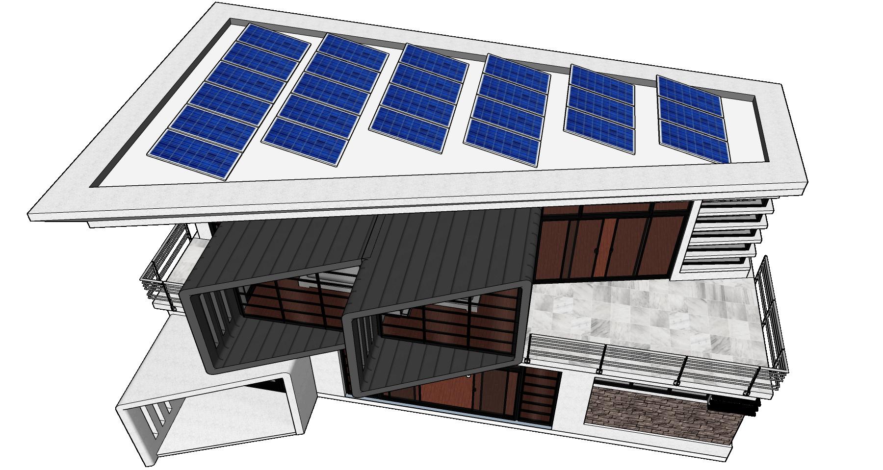
Step 1: Design and Installation of your PV system
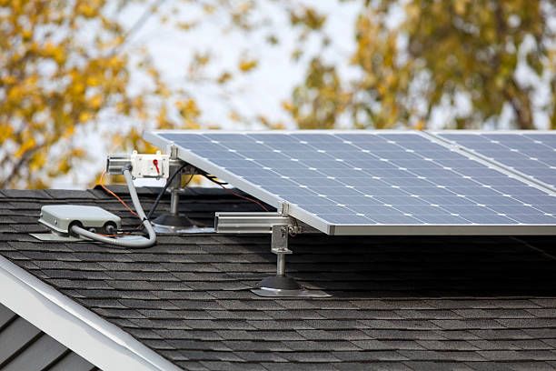
? You are at this stage currency where your PV plant has successfully been installed and waiting to be commissioned depending upon the type of system that you’ve installed, that is, On-Grid or Off-Grid.
Step 2: Commissioning of your PV System
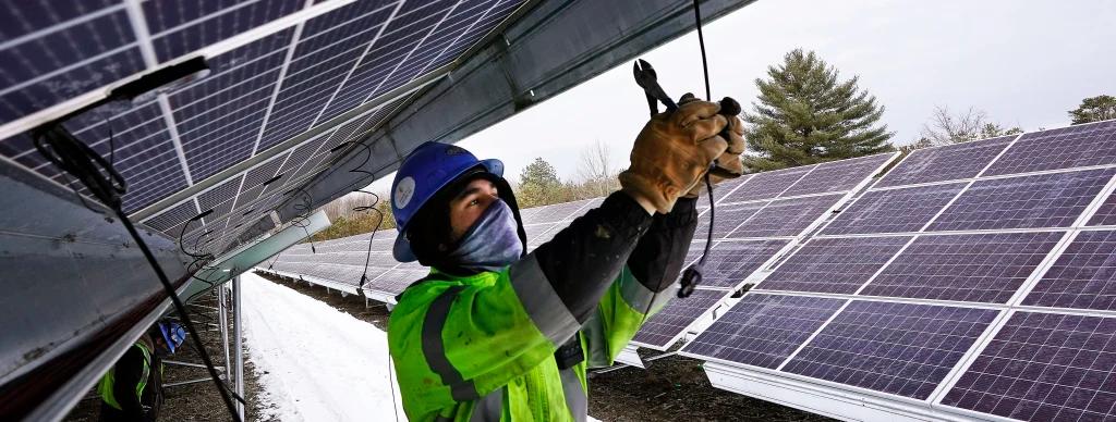
After the solar power plant has been installed there are a series of tests occurs before an SPD (Solar power developer) applies for net-metering or power evacuation to the power distribution companies (DISCOMs) which are as below.
Pre-commissioning Checklist for a Solar String Inverter.
In the case of Solar string inverters, the inverter will have multiple MPPTs and Multiple string inputs designed according to the given MPPT. Let's say we have a 330Wp PV panel, a 10kW inverter with two MPPTs, and three string inputs (2×1).
The inverter input will vary depending on the manufacturer. Now, the system will have 30 Nos of panels with 9.9kW DC input(30*0.330=9.9kW).
Before connecting the grounding links as a single string, the installer must check the panel-to-panel and panel-to-earth grounding links. The string calculation will involve, the open circuit voltage of the panel and the maximum MPPT input voltage of an inverter. Consider a 330Wp panel with a Voc of 45V and a Vmax MPPT of 1000V. The string sizing would be the number of panels multiplied by Voc which should not exceed the inverter Vmax MPPT i.e., 1000v. Ground Fault check. Before connecting it to the inverter, the installer must check the string for ground faults between the positive and negative end of the string and Voc between positive to earth and negative to earth. Let’s say the installer has given two strings 15 panels in one string and another 15 in another string.
On a Properly Earthed System:
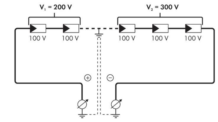
➢ The Voc between +ve and -ve is 675V(15*45V=675V) hence the +ve to earth should be less than 60V on a floating value. Likewise, to Negative to earth. If all measured voltages are stable.
➢ The sum of the two voltages with respect to ground potential is approximately equal to the voltage between the positive and negative poles. Let’s say, +ve to earth is 225V and -ve to earth is 450V. As a result, the system has a ground fault. By finding the ratios between these two voltages, the installer can identify the fault. PV connectors, DC cables, and PV modules may be damaged.
Does the example show a ground fault between the second and third PV modules?
Pointers:
- Now from the DC side, the strings are checked for grounding issues.
- Make sure the MC4 connector is properly crimped. These carry high DC voltages.
- We all know loose contact in an electrical system is a very good friend of fire. The majority of loose contacts occur on the AC side.
- Installers should not compromise system balance to reduce costs. Safety first is the first principle of engineering.
- Do not miniaturize the AC wiring to reduce system costs. For a 10kW inverter, the maximum single-phase output current is 14.5 Amps. Therefore, the system clearly needs cables with the same or larger cross-sectional area to drive the current without stress.
- Always consider distance when choosing AC wire size. The longer the distance, the greater the voltage loss. Use high-density AC cables, for long distances.
- When crimping AC terminals, the AC ground ferrule must be properly installed and properly insulated according to the manufacturer's instructions in the installation guide. If a system is a well-isolated system, then it is a best-case scenario.
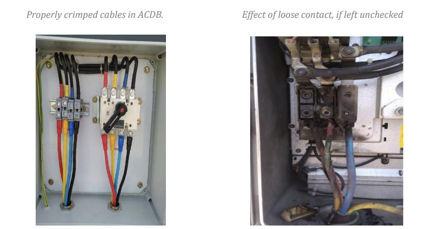
- A loose connection does not affect the inverter immediately, but over time the heat build-up can damage the cable and lead to a fatal fire. To avoid these events, perform regular checks.
- Ensure that the designated protective devices are properly connected to the system.
- Since the inverter is an expensive component, the protection functions should be well-enabled. The installer cannot compromise on the quality of protection.
See Also: Solar Panel Connectors: Past and Present Trends
In addition to the details above, all electrical equipment must be grounded. Electrical system grounding is provided to reduce fault leakage currents and ensure installation safety. This dangerous fault current can occur for many reasons, so it is very important to ensure that the system is properly grounded according to the guidelines of the IEC standard. According to IEC 60364-7-712, solar system grounding falls into two main categories: DC side and AC side.
DC Grounding
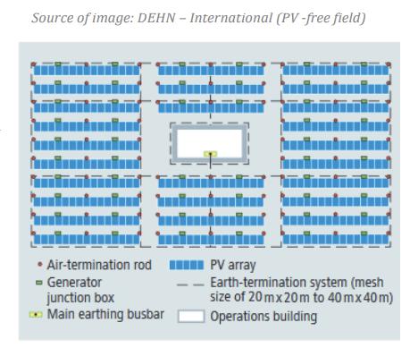
- The installer must ensure that a surge arrester is provided throughout the system, properly connected to a separate grounding pit and that the resistance is less than 10 ohms per IEC 62305-3.
- The installer must identify and visually inspect all relevant components for damaged or broken panels or cables.
- Bay-to-bay grounding and bay-to-structure grounding should be verified.
- The building ground is connected to a flat strip ground rod and routed to the ground shaft.
- The layout of ground cables and ground straps depends on the maximum short circuit current of the system. Installers should check the maximum short-circuit current of PV modules and PV generators.
- The number of pits provided for the system depends on the capacity of the power plant and the area covered by the components involved.
- For a properly grounded system, the resistance of the earth pit should be less than 2 ohms. The installer should check the resistance with an ohmmeter and make sure it is less than 2 ohms.
AC Ground
- The grid-connected inverter will not generate power if it detects an insulation failure from the PV module or if there is a ground fault on the grid side. If the AC voltage reference is not available or does not fall below specified limits, it will be disconnected from the generator (see IEC 62116). (Refer to ground fault test procedure to identify PV module insulation failure)
- The installer checks his AC voltages phase-to-phase, phase-neutral, and neutral-earth, and all of these are needed. The value should be under the standard parameters for each country. Make sure the ladder is covered with glands to protect it from insects and pests.
- The N-E value is less than 5 V in a properly grounded system.
- The inverter body must be grounded to avoid danger to persons who come into contact with the inverter body.
Cable Insulation Resistance Test.
Another source of ground faults is wiring holes. A visual inspection of the AC and DC conductor cables should be performed. Sometimes you cannot see it with your bare eyes.
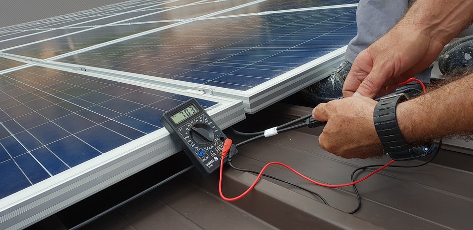
- The installer should therefore check the insulation resistance of the cable using an insulation resistance measuring device (ohmmeter) before commissioning.
- The needle shows 0 if there is a short circuit inside the conductor and shows infinity if there is an open circuit. When the cable is cut.
- Each cable, AC and DC carrier conductor in the system must be tested before connecting to the load. If the system is not grounded and connected to the load, it will leak current or contact the path of least resistance, seriously damaging personal safety and connected equipment. That's why the earth is so important. After ensuring that all pre-checklists have been completed and verified, the installer can commission the inverter.
Inverter Setup:
- The inverter should be commissioned according to national grid parameters.
- The user interface for each inverter varies by manufacturer. Initialization and setup of the inverter are also described in the installation manual.
- Most installers leave the system without commissioning after checking the inputs and outputs. The inverter works fine, but if you don't set it up, various events will occur that will interfere with power generation.
- All plug connections and cables should be checked regularly. To ensure stable power generation for the next 25 years, we should not stick to product quality.
How Waaree can Help?
PRODUCTS OFFERED
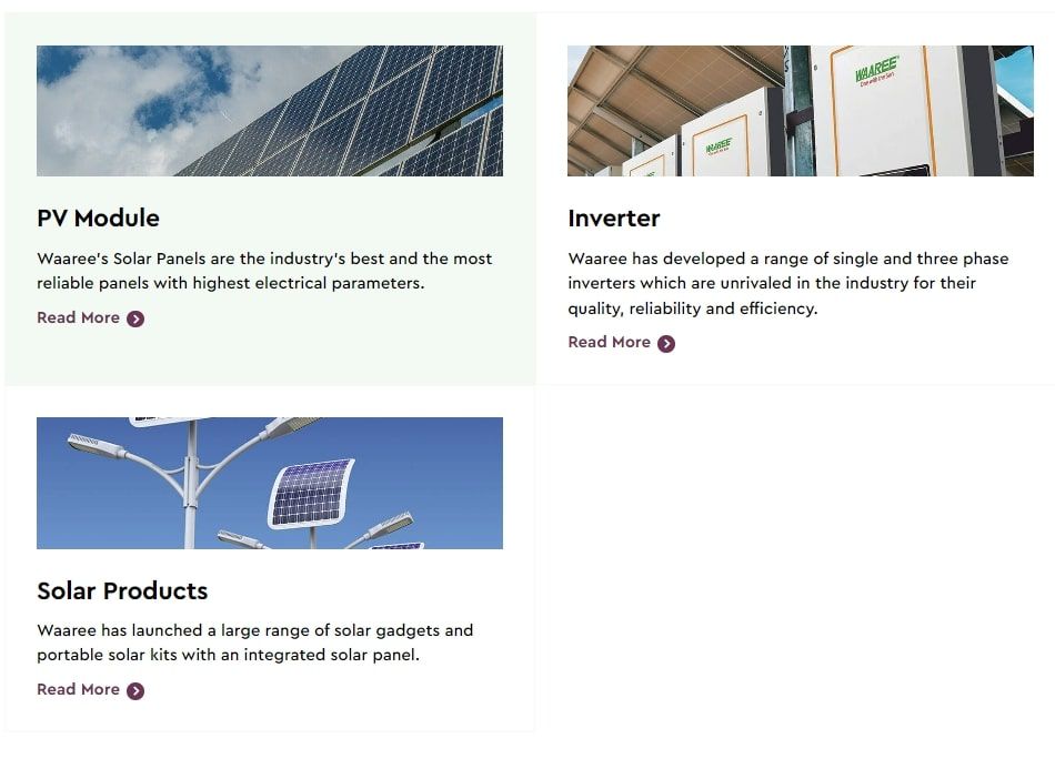
Waaree Energies Ltd. is the flagship company of Waaree Group, founded in 1989 with headquarters in Mumbai, India. It has India's largest Solar panel manufacturing capacity of 5GWs at its plants in Surat and Umbergaon in Gujarat. Waaree Energies is amongst the top players in India in Solar Panel Manufacturing, EPC Services, Project Development, Rooftop Solutions, and Solar Water Pumps and is also an Independent Power Producer. Waaree has its presence in over 380 locations nationally and 20 countries internationally. Step on to your cleaner journey by contacting us at 18002121321 or mail us at waaree@waaree.com
Read Further: Step by Step Guide for Solar Panel Installation in 2023
