









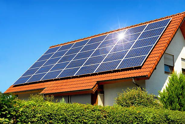
We in our previous blogs have given our readers a lot of information on the technical and commercial aspects revolving around solar module. It was however also important to educate our readers on few aspects of power plant designing. While already in our previous blog “What happens in Rooftop site survey?” we gave you the first hand basic information required to assess any site, it was important to also educate our readers on the next important step i.e. sizing of a solar power plant. Sizing of the solar power plant gives us an overview of the power plant along with their brief technical details. It also allows the consumer and the end developer to understand what would be the approximate investment required in such power plant. If you already have a rooftop solar plant installed at your place, you may just refer to this blog to re-confirm the correctness of the size of your plant. However if you are a novice and want to understand how do we size a solar power plant, you are at the right place. This blog would also inform you on few in-depth precise considerations for your power plant.

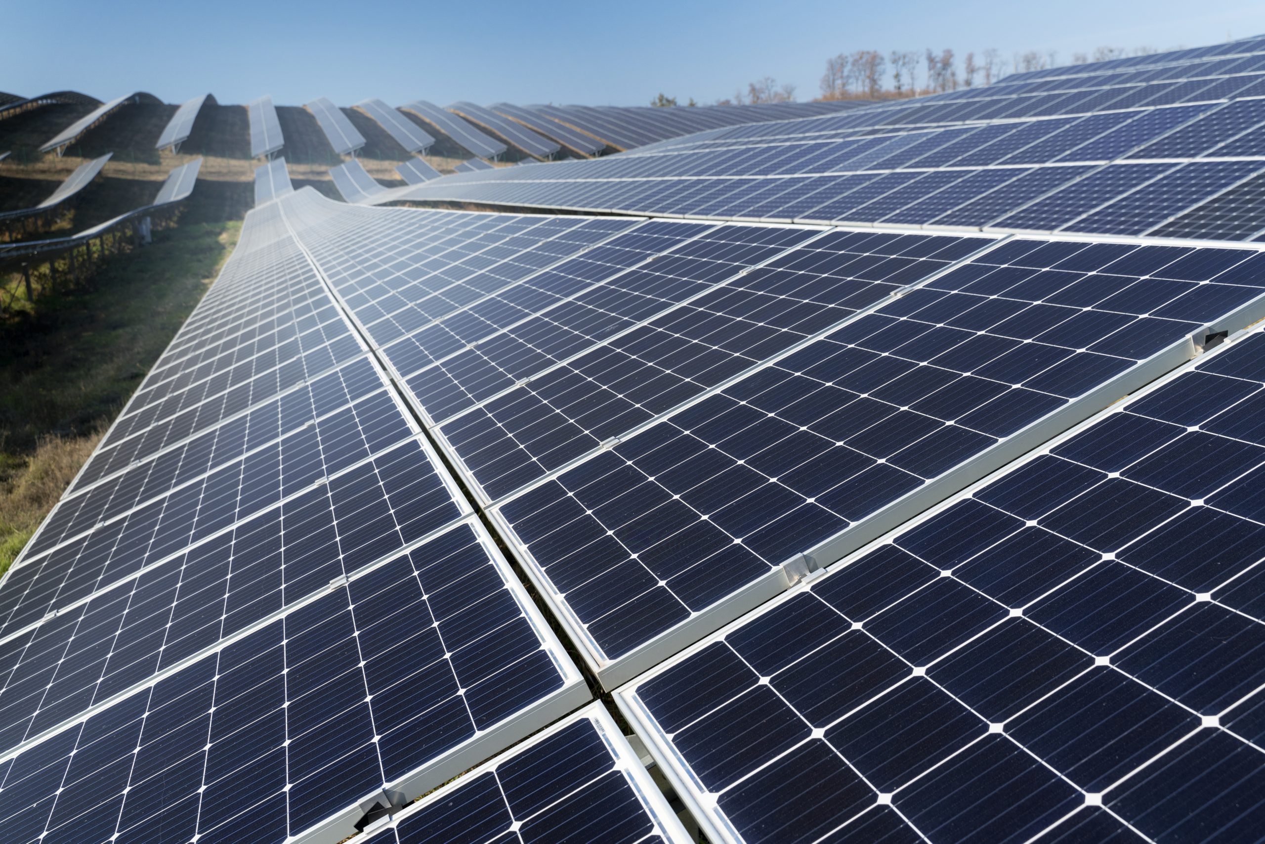
Figure 1: Rooftop power plant installed by Waaree Energies
The first and foremost step of sizing the power plant is estimating the load (and energy) of the place. While it may sound simple, such estimation is crucial to the entire process as it determines (approximately)the amount of power and energy the solar power plant is required to produce on daily basis. It also gives important information on critical and non-critical loads at the particular place giving us beforehand information on which load need to be prioritized in case of power outrage (for an off-grid systems only). The estimation of load for a typical household is given in the Table 1 as below:
Table 1 : Load estimation for a typical household
| Load | Number | Working time (Hour) | Power (W) | Energy reqd. (W-hour) |
| Tube-light | 2 | 6 | 40 | 640 |
| Fan | 1 | 10 | 60 | 600 |
| Refrigerator | 1 | 7 | 160 | 1120 |
| TV | 1 | 4 | 140 | 560 |
| Computer | 1 | 3 | 220 | 660 |
| Total daily requirement | 620 W | 3580 Wh | ||
The above considerations are based on normal consumption. It is noteworthy that such consumption varies from season to season based on location. Hence a PV system should be designed for worst case scenario i.e. when it is required to provide maximum power say in summer for a household. A PV system is considered to be reliable if it can meet the maximum demand efficiently.
The second step in sizing the plant is to determine the inverter rating. In an off grid solar system, the load is met by the available power in the battery bank via inverter (in case of AC loads) or a DC-DC converter in case of DC loads. The inverter/converter selected is to be based on its capacity to handle both input & output current & voltage. Typical input characteristics of a solar module are 12V to 72V and 1A to around 20 – 40A. The output however may be fixed at 220V AC 50/60 Hz (based on the standard grid frequency of your country). Assuming that all the load here (in above example) is AC, we need an inverter whose total power handling capacity is 620W. As inverter with such exact rating is not available in the market, we select an inverter with capacity close to the power requirement which is either 500W or 750W. However considering future expansion, we may select 750Wp inverter. Some energy is lost while converting power from DC to AC by an inverter. The efficiency of normal off grid inverters are in range of 93 – 98%. Considering 95% efficiency, in order to meet the energy requirement of 3580 Wh, the required supply at inverter is
| Energy required = | 3580 | = 3768 Wh |
| 0.95 |
The third step is to determine the battery bank size. While there is a push to adopt and utilize Li-Ion battery, lead acid battery still holds considerable chunk of market and hence they are considered here. The currently in use battery comes with 12V, 100/120 Ah capacity with maximum Depth of Discharge (DoD) (DoD means what is the maximum capacity of battery which could be used before recharging it) of 70%. This means that firstly the system can have voltage in multiples of 12V i.e. 12, 24, 36, 48V & so on and secondly the useable capacity from the battery of 120Ah is only 84 Ah (120Ah * 70% DoD). In order to minimize the heating (I2R) losses in wires, one would like to have a maximum system voltage possible, but such system would higher number of battery (and PV Module) to be connected in series which may incur significant cost. Hence a balance between cost and system loss is needed. In general, a system of 24V is considered for this example (one may increase it to 36 or 48V too). Now we determine the charge capacity required for our battery bank by
| Charge capacity of battery bank = | Energy required | = | 3768 | = 157 Ah |
| System voltage considered | 24 |
The required number of battery to generate such charge is found be
| No of batteries required in parallel = | 157 | = 1.86~ 2 batteries |
| 84 |
| No of batteries required in series = | System voltage considered | = | 24 | = 2 batteries |
| Voltage of battery | 12 |
Thus the battery bank must have 2 batteries in series and parallel in order to sustain the given load. However as we had mentioned earlier, we design the PV system for worst case scenario. Here, we consider battery autonomy i.e. the battery is required to supply energy in case of worst/ cloudy weather when there is almost no sunlight throughout the day. Considering 3 days autonomy, we need 3 more sets of 2 x 2 (series x parallel) battery interconnected with each other. Thus the battery bank would be as shown in Figure 2 :

Figure 2 : Single line diagram of battery bank
Also read: Heterojunction – The technological way ahead for solar PV!
The next step is to determine what would be capacity and number of solar modules required. For determining this, first we need to determine what amount of energy is required from the panels. Such energy has to travel to battery via the charge controller. The energy required in our case at the battery is 3768 Wh. The efficiency of usual lead acid battery is between 80 to 90%. Assuming 85%, the energy required at battery is:
| Energy required = | 3768 | = 4433Wh |
| 0.85 |
The charge controller which is often coupled with battery in order to protect the battery comes with an efficiency of around 90%. Thus the energy required at charge controller is:
| Energy required = | 4433 | = 4925Wh |
| 0.90 |
Thus the energy required to be generated by the solar panels every day is 4925 Wh. However, there is still a catch here. The solar module when operated at higher temperature & settled dust primarily causing loss of energy (around 15 – 25%, can be as high as 30-65%). Thus finally the energy required to be generated is:
| Energy required = | 4925 | = 6156Wh |
| 0.80 |
Now we need to select the required module. We could actually use any module available however they should be efficient enough considering the amount of space utilized. We select Waaree’s mono module with a power rating of 330 Wp whose maximum voltage (Vmp) is 36.55V and maximum current (Imp) is 9.03A.The required voltage output from the module array is 24V and the selected module has 36.55V. In such cases, the charge controller would convert such extra voltage into current, hence we do not require any additional modules in series. The charge capacity required from the module array can be calculated as follow:
| Change Capacity = | Energy required | = | 6156 | = 168.42 Ah |
| Voltage of module | 36.55 |
Considering the average sunshine of 5 hours in a day, the required current output from the module array could be determined by:
| Current output required = | Charge Capacity | = | 168.42 | = 33.68 A |
| No of sunshine hours | 5 |
Hence the number of solar modules required to produce such current output (in parallel) are:
| No of solar modules in parallel = | 33.68 | = | 168.42 | = 3.73 ~ 4 modules in parallel |
| 9.03 | 5 |
The module array would look as shown in figure below:

Figure 3: Single line diagram of module array
The last step is to calculate the required cable for our system. The primary thing which needs to be kept in mind while selecting cable is the losses incurred while in operation. The losses (generally heat) depends on the resistance of the material used in cable which is given by:
Power Loss due to heat = (Current)2 x (Resistance) &
Resistance = Resistivity x Length of wire /Area of wire
It could be seen that the resistance depends on the length and area of wire (as resistivity is constant). Now we were to increase the length, the resistance and hence the power loss of the wire increases. Thus to limit that, we need to increase the area of the wire, however such increase comes with a cost. Thus one need to balance between these two factors. The power loss due to heat shall be in less than 2% the rated power/power generated by the solar module.
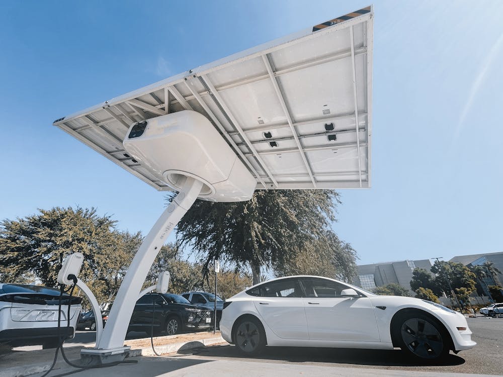
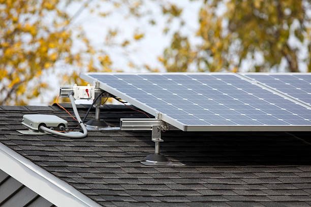
Thus this is how one can start from scratch and have a full design ready for installation. You can further install such system by either getting in contact with a reputed EPC contractor or by buying Do It Yourself (DIY) kits. Waaree Energies has an experience of executing more than 500+ MW EPC projects. We have also launched a DIY kit (Figure 4) named “Pronto – where one could install the system within mere 30 minutes.

Figure 4 : Waaree DIY kit – Pronto
Let us all pledge to make solar energy the primary source of energy in the near future.
RAHE ROSHAN HAMARA NATION
You can read: How does a BESS (Battery Energy Storage System) Work?